Thermal Imaging Technology Basics from MOBOTIX
Thermal imaging technology is a no-contact imaging procedure that makes it possible to see the thermal radiation from an object or body otherwise invisible to the human eye.
Thermal radiation is electromagnetic radiation emitted by a body based on its temperature. It is caused by thermal motion within a body’s molecules. This is the result of accelerated charges that emit radiation in accordance with the laws of electrodynamics. Thermal imaging technology captures and displays temperature distribution across surfaces and objects. Thermographic cameras usually display heat intensity information in artificial colours (blue = cooler, red = warmer). In terms of the number of pixels, the resolution is considerably lower than that for cameras capturing the visible spectral range.
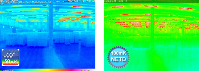
Unlike cameras with optical image sensors, one of the decisive quality criteria for a thermal camera is the camera’s ability to capture the slightest differences in temperature and to produce an image that displays these differences in colours. The NETD, or Noise Equivalent Temperature Difference, is used to measure the sensitivity of a thermal sensor and is expressed in millikelvin. With an NETD of 50 mK, MOBOTIX thermal cameras can visualise temperature variations starting at 0.05°C, which places them in the top range of cameras currently available for general use.
Thanks to an NETD of 50 mK, the MOBOTIX thermal image (left) shows significantly more details than a competitor’s less powerful thermographic camera with an NETD of 100 mK (right)!
Advanced, Cost-efficient and Powerful – Thermal Cameras from MOBOTIX
After successfully launching MOBOTIX Thermal Imaging Technology, MOBOTIX offers additional thermal cameras and thermal sensor modules with TR Technology and calibrated, industry standard high-end thermal imaging sensors with an NETD of 50 mK. TR stands for Thermal Radiometry, meaning that in addition to existing MOBOTIX thermal camera functions, the thermal radiation is measured across the entire image area, and a temperature value is assigned to each pixel. These measurements can be used to trigger an event based on the temperature increasing above or decreasing below an individually set trigger level (camera alarm, network message, activation of a signal output, etc.). The temperature measurement is accurate to +/-10 Kelvin based on the quantitative electromagnetic thermal radiation produced by individual objects within the camera view and/or within a defined TR measurement window. The accuracy of the temperature measurement depends on the emission ratio of the object being measured. This value is based on the material and surface area of the object in question. The ideal measurement object is a black body with an emission ratio of 1. Bare metals have a value of 0.1 and lower (objects with a mirrored surface generally have a low emission ratio). Further, the camera does not just measure radiation from the object itself, but also any radiation that is reflected back by other objects such as tables or windows.
Practical Applications For Thermal Radiometry (TR)
TR technology is used less for measuring the exact surface temperature of an object (simple temperature sensors can do this in a much more cost-effective way), but rather serves to recognise potential dangers from sudden increases or decreases in temperature and react without delay. These dangers may include smouldering fires invisible to the naked eye or sudden gas leaks. These type of events change the ambient temperature immediately, and MOBOTIX TR technology is able to detect and locate them so that they can be dealt with before any further damage is done. Another important advantage of MOBOTIX thermal imaging technology is that detection and measurement can take place at a distance of up to several hundred meters, meaning it can also monitor large areas and those difficult to access.
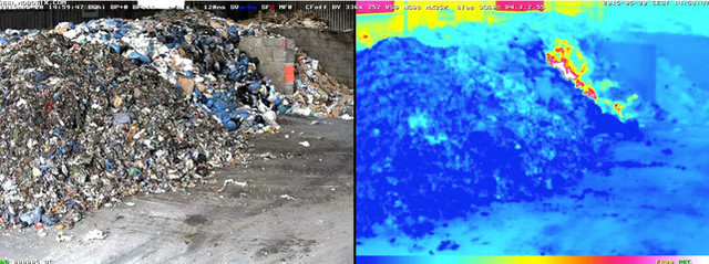
Smoldering fire in a garbage dump: The dangerous rise in temperature is clearly visible in the thermal image on the right. A MOBOTIX camera with TR technology detects and measures temperature ranges within the entire image (or in up to 20 different measurement windows) and can send an alarm instantly if the temperature reaches a limit set by the user (for example, 60°C/140°F).
Typical applications for temperature-related event
- Fire prevention and safety both inside and in an outdoor area (for example, detecting forest fires)
- Plant security and safety in production halls
- Monitoring machinery
- Use in food production and logistics
- Production, storage and transport of dangerous goods (gases, liquids, chemical products)
- Use at borders and in controlled areas
Configuration of TR settings via camera software (using a web browser)
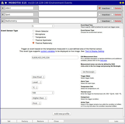
Selecting settings for temperature measurement/thermal radiometry takes place using camera software within a web browser. The new Thermal Radiometry event sensor is located in the Setup Menu under Event Control > Event Overview > Environment Events.
Just as with video motion events, or exposure windows, the first step is defining whether the temperature is to be measured across the entire thermal camera’s image or only in a (user definable) square TR window. An S15 with two thermal sensor modules can measure on both sensors at the same time. By creating profiles it is possible to activate up to twenty simultaneous TR windows per camera, which can overlap.
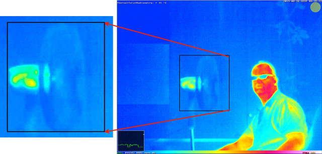
Thermal image with TR measurement window (black frame in the middle of the image): The green or red graph in the black box (scroll chart) on the bottom left, which can be displayed/hidden, gives an optical view of how close the value is to the trigger value (trigger level or average value in the TR measurement window). The scroll chart is based on the principle of an activity display on the MxActivitySensor.
At this point, the camera software is used to define when and how the event is to be triggered for each TR window (see image on next page). It will take place either when a single pixel (measurement mode: one pixel) or a certain percentage of the entire measurement window exceeds or falls below the defined temperature level.
Possible valid values are any whole number within the range -40°C to 550°C (-40°F to 1022°F).
Important for installation: Thermal radiation does not penetrate glass panes
Both the protective screen and the lens are made using germanium, a semiconductor material, as standard glass would reflect infrared thermal radiation instead of allowing it to pass through to the sensor. If there is a glass pane between the thermographic camera and the object to be detected/measured, the camera can no longer detect thermal radiation. The solution: Use of a second optical sensor module (with M15-Thermal or S15).


